April 11, 2026Energy / BMS
BMS-Web — My Multi-BMS Dashboard for JK-BMS with Telegram Alerts
JK-BMSLiFePO4ESP32-S3MQTTHome AssistantTelegram Bot
Advertising note: This post contains affiliate links (marked with *). If you buy through them, I receive a small commission — the price stays the same for you.
Safety notice — rebuild at your own risk
Lithium / LiFePO4 batteries: Incorrect wiring, short circuit or improper charging can cause fire, gas release or explosion. Protective electronics (BMS) are mandatory. When in doubt, consult a professional.
Rebuilds at your own risk. This description is a personal documentation, not a verified build guide — you have to verify suitability for your use case yourself.
Why a Custom BMS Dashboard?
I run two LiFePO4 batteries with 8 cells and 280 Ah each, each monitored by a JK-BMS (JIKONG B2A8S20P-HC, 200 A, 2 A Active Balance). The official JK-BMS app covers the basics, but has three limitations for my use case:
1. Only one BMS at a time. Comparing both batteries side by side is not possible in the app.
2. No alerts, no history. The app only shows live values. Cell drift, offline states or BMS errors are not reported. Data from past days or weeks is not available.
3. No integration. The connection is Bluetooth-only, directly to the BMS. No MQTT, no Home Assistant, no integration into other systems.
To address these requirements I built BMS-Web: a multi-BMS web dashboard with live data, history, energy counting and a Telegram bot.
The Hardware: One ESP32-S3 for Both BMS
On the hardware side, a single ESP32-S3 is used. It runs ESPHome and uses the `jk_bms_ble` component, which implements the JK-BMS Bluetooth protocol. An ESP32-S3 can hold multiple BLE connections at the same time — in my setup, both JK-BMSes in parallel.
Data flow:
1. JK-BMS transmit via Bluetooth Low Energy (BLE) to the ESP32-S3
2. ESP32-S3 receives, decodes and publishes via MQTT over WiFi
3. BMS-Web server (Node.js) subscribes to the MQTT topics and maintains state
4. Browser and Telegram bot display the data live
No additional bridge, cable to the BMS or RS485 adapter is required. The ESP32-S3 only needs to be placed within Bluetooth range of the batteries.
Hardware actually used:
- **JK-BMS JK-B2A8S20P-HC* — 4S-8S, 12V-24V, 200 A, 2 A active balancer with supercapacitor, Bluetooth + CAN + RS485, heater. Installed on both batteries.
- ESP32-S3 DevKit-C (N16R8)*** — 16 MB flash, BLE 5.0. One board is sufficient for the parallel BLE connection to both BMS.
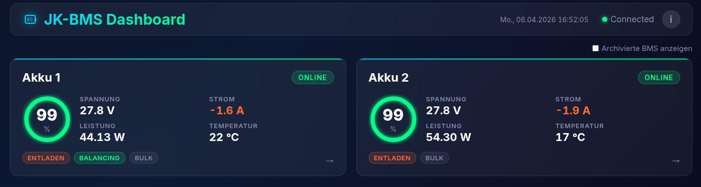
Multi-BMS at a Glance
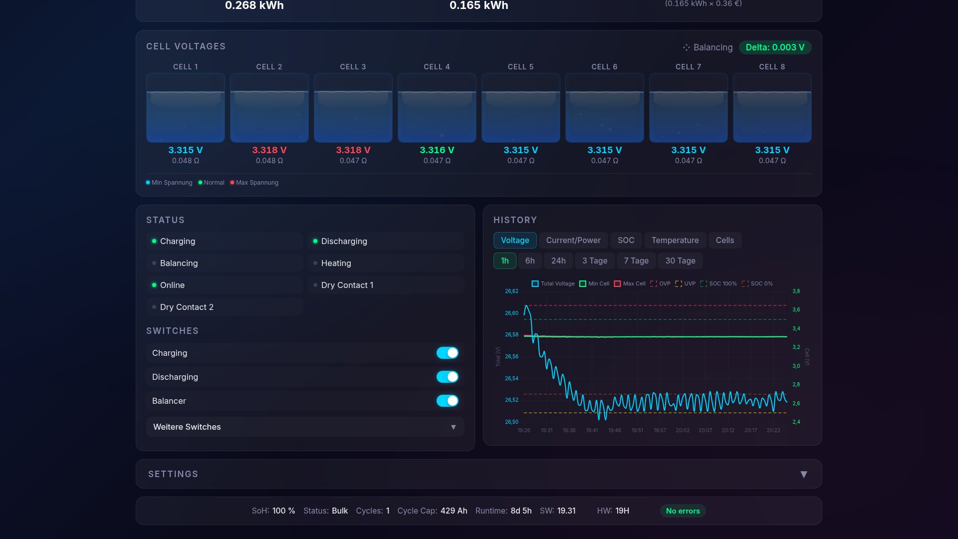
The home page shows an overview view with both batteries side by side. Each card contains SOC, voltage, current, power, temperature, cell delta and balancing status.
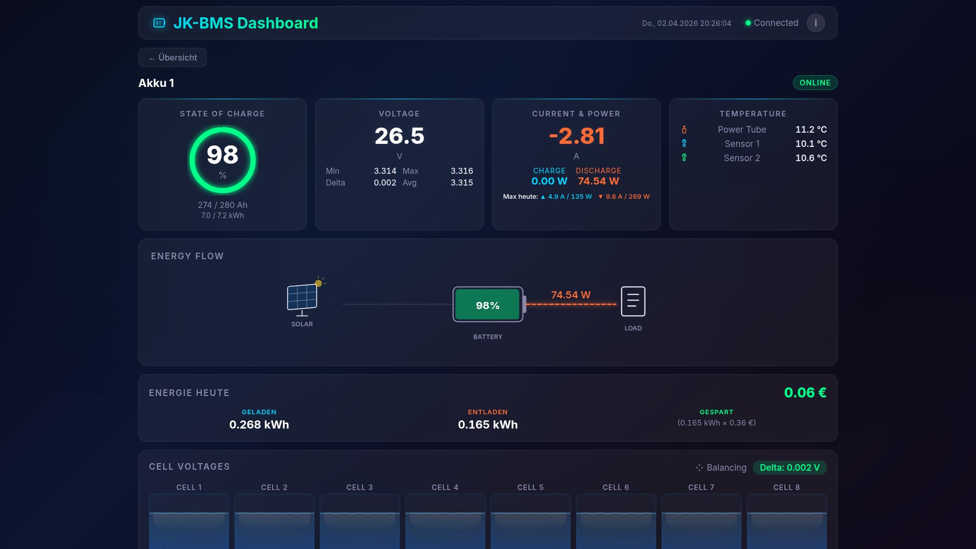
Clicking a card opens the detail view with:
- a large SOC ring including Ah capacity and kWh
- all 8 cell voltages, color-coded (blue = lowest, red = highest, green = normal)
- both BMS temperature sensors and the power tube temperature
- switches for charge, discharge and balancer
Below follow charts with dual Y-axes, zoom/pan and time ranges from 1 hour to 30 days. Voltage, current, power, temperature, SOC and balancing current are displayed. Data points are stored every 30 seconds in a MongoDB history collection and queried from there.
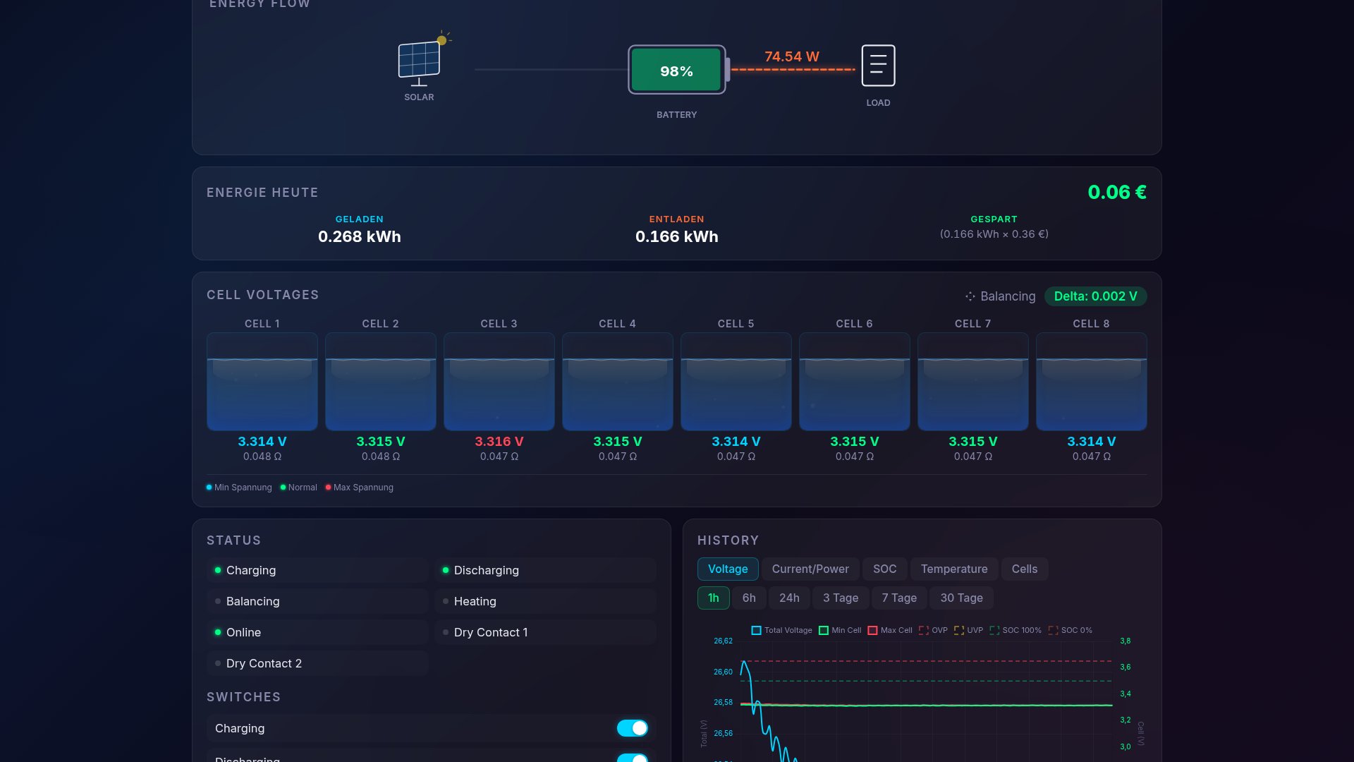

Balancing Display in Detail
The JK-BMS uses an active supercap balancer. Instead of dissipating energy in resistors (passive balancing), charge is transferred via a supercapacitor from the highest to the lowest cell.
The BMS publishes a `balancing_sensor` value with three states via ESPHome:
- 0 — off
- 1 — phase 1: supercap charging from the highest cell
- 2 — phase 2: supercap discharging into the lowest cell
In addition, the cell number of the current highest and lowest cell and the balancing current are transmitted. BMS-Web visualizes this information as follows:
- ▼ Orange arrow above the highest cell (charge outflow)
- ▲ Cyan arrow above the lowest cell (charge inflow)
- current balancing current as a numerical value
This makes it possible to see whether the balancer is active, in which direction charge is being transferred and which cell is currently being equalized.
Energy Counting and Daily Stats Persistence
The BMS provides voltage and current. BMS-Web calculates the power from these (`P = U × I`) and integrates it over time into energy values — separated into charge and discharge. At midnight, the counters are reset.
The following daily values are displayed below the SOC ring:
- Charged today in kWh
- Discharged today in kWh
- Saved today in euros (based on a stored electricity price)
To make sure daily values survive a server restart, BMS-Web writes the current state to the MongoDB collection `daily_stats` every 30 seconds. On startup, the server reads the last values back and continues counting. Daily maxima (peak power, peak current) are persisted and restored the same way.

Telegram Bot: Alerts, Remote Control and User Management
BMS-Web integrates a Telegram bot that both sends alerts and serves as a remote control.
Automatic alerts:
- SOC < 5 % (critically low state of charge)
- Cell delta > 70 mV (cell imbalance)
- OVP / UVP violation plus pre-warning when a cell approaches the limit
- Overtemperature (MOSFET or cell temperatures from 65 °C)
- BMS offline (MQTT stream interrupted, connection to the ESP32-S3 lost)
- BMS error bitmask (any error code from the BMS)
Alerts use a 5-minute debounce to avoid duplicate notifications.
Remote control: The bot shows a persistent reply keyboard with Status, Battery 1, Battery 2 and the admin menu. Inline keyboards allow the charge, discharge and balancer switches to be toggled per battery directly from Telegram, without opening the web UI.
User management: New users have to be approved by the admin. Alert delivery can be activated or deactivated per user individually.
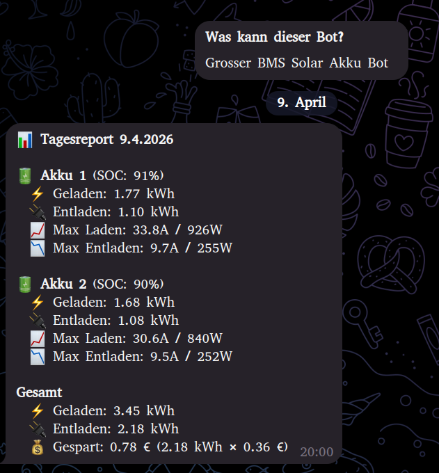
Daily report: Every evening the bot sends a report with charge and discharge per battery in kWh, the daily maxima (peak current, peak power) and a total summary including savings in euros.
Case Example: Cell Over Voltage Alert
An example from regular operation illustrates how alerts and remote control work together.
During a charging process on battery 2, one cell reached the upper voltage limit while the remaining cells were still below — a typical case of cell drift where the balancer cannot keep up with the charging current. BMS-Web sent a Cell Over Voltage alert via Telegram.
Using the inline button in the Telegram chat, I disabled charging for this battery. Charging was switched off at the BMS, the balancer kept running and gradually equalized the voltage of the drifting cell. After about an hour, the cell delta was back in the normal range, after which I re-enabled charging via Telegram.
*Note: A screenshot of this specific event is not available, as Telegram automatically deletes older messages in my chat history after a few days. The daily report screenshot above shows the bot communication as an example.*
Comparison with Commercial Solutions
Commercial solutions such as Victron, BYD or Pylontech cover similar requirements. For this use case, the following points argued for a custom build:
Costs: A Victron Cerbo GX is around €800. The setup described here consists of the already installed JK-BMS, one ESP32-S3 (~€10) and the NUC that is running anyway as a server. Additional hardware cost: around €10.
Configurability: The scope of displayed values, alert thresholds, visualization and Telegram integration are freely configurable. There is no dependency on cloud services or vendor-specific apps.
Home Assistant integration: Communication runs entirely over MQTT and is therefore integrated into Home Assistant without additional configuration. Automations can be built on top of it, e.g. charge control based on SOC and PV yield.
Access to raw data: All measurement values, including balancing phase and cell drift, are directly accessible and traceable via the history.
Requirements for replication: at least one JK-BMS with BLE, one ESP32-S3 and a small server (NUC, Raspberry Pi or similar) running Node.js and MongoDB. The ESPHome configuration is open source (syssi/esphome-jk-bms). A release of the dashboard itself is under review.

More technical details about this project:
View Project →* Advertising — Links marked with an asterisk (*) are affiliate links. If you purchase through these links, I receive a small commission — the price stays the same for you.
Mike Sobczinski
Embedded developer and shift worker in the semiconductor industry. Builds IoT solutions with ESP32, LoRa, and Home Assistant — from firmware to dashboard.
Learn more →